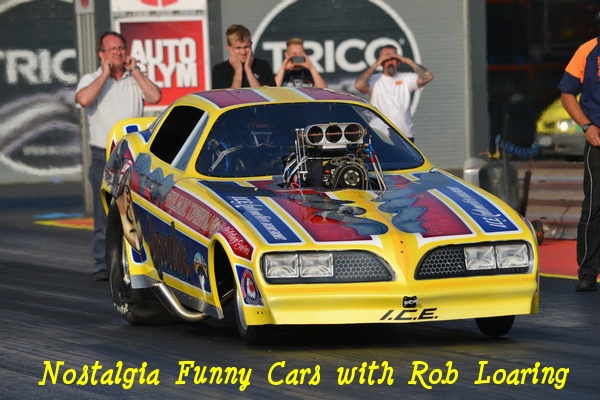
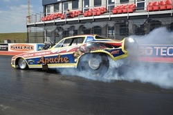
 As told to Friday 23rd October 2015: End of part one With the 2015 season now behind us we feel that development of the first version of the Apache Funny Car is pretty much done. I'm sure there are smarter people that can take it further but our group feels that for us, there's little more than four or five hundredths left on the table. Two years after the car débuted at Dragstalgia 2013 the ET and speed marks stand at 6.13 seconds and 224 mph. The best eighth mile numbers are 3.99 seconds at 188 mph. For the benefit of those that have followed the car from the beginning there have been two significant changes to the initial specification, both of which were carried out by May 2014. The rear gear ratio was changed from 3.89 to 4.11 and the fuel pump was switched from the Enderle 1200 to a Rage 1400N. It's been an interesting exercise for the whole team and in writing this Blog, it has been my intention to put some accurate numbers to running costs and basic set up. Subsequent to Dragstalgia 2015 the specification was revised and the nitro percentage was increased. At the National Finals the ET dropped to 5.96 and the speed mark increased to 235 mph, but that's another story... Cost As indicated in the first Blog entry I feel that there are many ways to calculate the cost of running a race car. If one were to account for such things as time lost at work, wear and tear on tow vehicles, depreciation in the value of motor homes or caravans it's possible to make running even a modest ET car look out of reach. Having discussed with Tim and Perry the possibility of running a Nostalgia Funny Car, the number they were interested in was how much 'more'. Here in the UK there are a great many people that run fast blown alcohol cars. Most of them accept that any financial compensation they might receive will be of little or no consequence to their running cost. The number that both Tim and Perry wanted was the cost difference between running a car of this type and running an NHRA-legal Nostalgia Funny Car. We'll take the three major expenses, clutch, fuel and oil one at a time. Clutch As soon as our test program allowed us past the eighth mile it looked as though our clutch budget was going off the radar. The general set up, cost and technical details of our clutch, as well as our durability targets are all covered in the second Blog entry. In short, we were looking for fifteen runs from the two floaters and ten runs from the friction discs. To understand why our clutch problems caught us, a brief explanation of our test procedure will probably help. There's nothing fancy here, just common sense. First off we set a target ET and then work back to estimate what the 60' and 330' (short) numbers should be in order to achieve it. If the short numbers aren't there the ET simply won't happen. Having just spent a small fortune on paint, the first job with the Funny Car was keeping the blower on and the body in one piece. With our 426 Hemi the fuel pump is driven directly off the engine and its output is linked to engine rpm. Initially we were simply looking for the engine rpm to climb to a level where the fuel pump output was adequate before there was any significant reading from the G-meter.


The reason for this was to ensure that the engine had sufficient fuel volume before it saw any load. Each new fuel pump is delivered with a flow sheet which indicates rpm vs flow volume, this allowed us to set an initial rpm target. That is, the desired rpm to which the engine will climb immediately after Tim snaps the throttle open. The actual fuel volume running into the engine can be viewed after the run and is read directly of off the fuel flow meter. As we new the weight of the car and the data logger is equipped with a G-meter, we were able to take a punt at engine load. Our initial target rpm was somewhere around 6,000 and all that was required to set this were a few short runs lasting six to eight tenths of a second. With a wide open throttle time this short, unless we had missed by a mile, the engine was in no danger of being damaged. If I recall correctly, it took two runs at our Dragstalgia début and maybe one or two hits at the following test session to get the first hundred feet straightened out. By this point the car had gone 1.04 at 60' and the first short number was in place. This process continued for three or four test sessions. The 330' target was 2.78 to 2.82s and the 1/8 mile number was anything in the mid 4.20s. When all the short numbers were in place Tim made his first full pass, 6.43 at 218, and our database looked pretty healthy. This approach gave us both direction and magnitude. By this, I mean we then had a clear indication of the cars behaviour and also what represented both a big change and a small change. In race car development, if you're trying to move forward, it helps to know where you've just been. Back to the clutch. During the short runs and even up to the eighth mile the clutch wear was minimal. Tim shifts the car just after the clutch has locked, usually somewhere around 450 feet. The shift starts the clutch slipping again but as the runs were stopping at the eighth, this second round of slippage was very brief. Our durability targets looked quite realistic and the car was smooth. The first thousand foot pass gave us a taste of what was coming. After the initial lock up the clutch temperature is high and unfortunately, it didn't fare too well as it slipped again down the back half. Large pieces of friction material started breaking off and discs were being scrapped. Another problem was the resulting vibration caused by a clutch that was now running way off balance. During this period we were changing a rear main bearing every time the car went down the track. Around this time we had changed from a 3.89 to a 4.11 rear and the clutch was set quite soft. We were concerned about aborted runs and had been prepared for some high clutch wear, however, this was way too much. Our initial response was simply to reduce clutch slippage until the car became either difficult to drive or inconsistent. Over the next few test sessions we kept loading on counterweight and waited for the car to protest, fortunately, it didn't. As a result our clutch program is now very healthy. We have several packs, each of which can make two runs before being serviced. The steel floaters start off around .365" thick and after two runs they show minimal wear. At this point they are ground .004" to .006" to bring them back into shape. When they get down to .270" they make two more runs then they're done. The friction discs start off a little thicker but it usually takes a little more to clean them up. At .260" to .270" they make one or two more runs, the centre hubs are then removed and the rest goes in the bin. The cost of the steel floaters has increased slightly but purchasing the friction discs without drive hubs and re-using the old ones has brought their cost down. Our clutch costs are now pretty much where we'd hoped. The floaters are about £150 each and there's two in a pack. We get fifteen to twenty runs out of a pair so the cost sits at around £18 per run. The friction discs are also around £150 each and there's three in a pack. We're now getting at least ten runs from a pack which gives us about £45 per run. By the time we factor in some fasteners and a few grinding wheels we're pretty comfortable that the clutch costs us about £70 per run. Fuel No great surprises here and we're pretty well on budget. The cost started to get away from us a little but we've changed our warm up procedure and everything is now back in line. From the start we elected not to warm the engine on methanol. A number of teams choose to do this and if we ran a blower with no Teflon or one that was quite well worn it's something we'd probably consider. The usual technique is to push a nylon pipe into a port that is positioned above the blower and drop the other end into a drum of alcohol. When the engine is started on petrol the blower pulls fuel from the drum and the engine runs quite happily. The reason we choose not to do this is lubrication. During normal operation, the idle fuel that runs through the eight Hat nozzles also lubricates the blower rotors. These eight nozzles are distributed along the length of the blower and in our opinion do a better job of lubricating the rotors and seals than running fuel through a single nozzle. There is an alternative but it adds equipment and complexity to an already full and busy trailer. Some teams use a pressurised tank which contains a siphon tube. The tank is maybe 24" tall, 8" in diameter and has a -6 fitting fixed at the top. Also attached to the top is a tyre valve and a pressure gauge. One end of a length of hose is connected to the -6 fitting and the other end is attached to a gate valve which is in turn connected to the distribution block that sits on the back of the blower. This distribution block feeds the eight nozzles that sit above the blower and the warm up procedure goes something like this. The tank is half filled with alcohol and the gate valve is closed. A foot pump is then attached to the tyre valve on top of the tank and the whole thing is pressurised to around 8 to 10 psi. Once the engine is running on petrol (sprayed straight at the Butterflies from a squeezy bottle) the gate valve is slowly opened and the compressed air pushes the alcohol up the siphon tube through the gate valve and out of the eight injectors sitting over the blower. By modulating the gate valve it's possible to control idle rpm and the blower is lubricated pretty well. The downside is complexity. Also, someone has to watch the tank pressure as hooking it to an airline, regulated or otherwise, is a recipe for disaster.


Our warm up procedure goes something like this. We have a modified oil pan which carries a one inch diameter tube running along its length. This tube has one end capped and several holes are machined that direct air up into the crank case. The other end of the tube is attached to a hot air gun. Any time the ambient temperature is low, this oil pan is attached to the engine and the hot air gun is fixed to the open end. First thing in the morning the gun is set to 'Low' and run for about an hour. An oil heater attached to the dry sump tank is also run during this time. On the subject of oil temperature, attempting to put heat into a cold engine with pre-heated oil is absolutely futile. As soon as the engine is fired the oil temperature will plummet back down to a few degrees above ambient and the resulting change in engine temperature is so small it's irrelevant. If you're serious about pre-heating you need to address the major components. When the gun has run for about an hour all of the engine internals are warm to touch and the regular oil pan is fitted. Before the car is fired we connect a timing light and a hand held monitor which gives us all the data that is seen by the logger. As soon as the engine is running the idle fuel flow is dropped from 1.7 gallons per minute (gpm) to .75. This is done by partially opening the fuel shut off while checking the flow rate displayed on the monitor. One of the team will run a stop watch to monitor how long the engine has run and this lean period will last for between 90 and 100 seconds. During this time Tim will check the clutch and transmission and a crew member will check ignition timing. After roughly a minute and a half the fuel shut-off is closed and the fuel flow returns to 1.7 gpm, Tim holds the brake and releases the clutch. We then whack the throttle a couple of times to seat the clutch and shut the engine off. The whole thing takes less than two minutes. Jason, our data guy, then downloads the logger while the rest of the team are dropping the car down off the stands and fitting the body. He'll check things like oil and fuel pressure against reference numbers and shout if anything looks odd. The cost of the fuel used in the warm up goes something like this. We have about a minute and a half at .75 gpm or 1.5 X .75. This gives us 1.125 gallons for the lean bit of the warm up. The rich part lasts no more than fifteen seconds so we get .25 X 1.7 resulting in about 0.425 gallons. On track, a typical run lasts about two and a half minutes. To establish the fuel cost we'll ignore the burnout and assume that the engine is either at idle or wide open throttle. If we put the idle time at two minutes fifteen seconds we have run time X flow rate at 2.25 X 1.7 which gives us 3.825 gallons. We'll be generous and say that the average fuel flow on the run is 19 gpm or about 0.32 gallons per second. For a six twenty we get 6.2 X 0.32 which gives us 1.98 gallons. To establish a final figure we just sum the lean and rich warm up bits and the idle and wide open throttle numbers. This goes 1.125 + 0.425 + 3.825 + 1.98 = 7.35. This number indicates 7.35 US gallons or, just under 6.25 Imperial gallons. The fuel cost is about £18 per Imp. gallon so we have an approximate fuel per run cost of 18 X 6.25 or something in the order of £115. Oil This is an easy one. The initial oil capacity of our engine was four gallons but with some oil system modifications we now have that down to 3½. In simple terms, while the fuel pump is operating, our oil lasts no more than five minutes. This means that 3½ gallons of oil is good for one warm up and one run. The oil cost is about £20 per gallon making the per run cost £70. The only time we get caught here is if there's a delay or a schedule change and we have to warm the car twice, in which case you can tag £90 on the per run cost. If there's a short delay and the engine temp is only a little low we just run it for fifteen or twenty seconds on the squeezy bottles.


Summary Blown alcohol cars also have an appetite for consumables. In our first blog entry we estimated that for our AA/A Altered, Havoc, a typical per run cost for clutch, fuel and oil was around £95. If we look at the Funny Car we have £70 for the clutch, £115 for fuel and £70 for the oil. This puts the total at £255 or, from a different perspective, £160 more than a typical middle order Blown Alky car. The 'Elephant in the Corner' here is damage. It might be that we've been lucky but at this point, after two and a half years, we've bent a few exhaust valves, burnt up some pushrod tips and snapped two blower belts. Apart from that we have a clean sheet. The two sets of pistons that we rotate between rounds are the same ones we started with in 2013 and they carry the same rings. The first two sets of rods we used were torqued so many times they were retired at about twenty five runs and now we're into our second sets. The tyres aren't happy at much over twelve runs but other than that, the Apache Funny Car is a pretty standard deal. However, I will say that we run a pretty tight ship. If we we're to get casual about this stuff these costs would increase dramatically. The clutch for example doesn't wear in a linear fashion. At two runs we might have 'X' wear, but four runs without servicing does not give us '2X', it's more like '4X' or '5X' so we have to keep on top of it. Changing our warm up procedure has allowed us to go from six to nearly eight runs from a barrel of fuel. With this car, it pays big to watch the details. Specification After Dragstalgia 2015 we brought the car home and went through it from one end to the other. The following data indicates how the car was run at this event and the Racepak screenshots are from the 6.13. The static compression and fuel jet numbers are included for general interest but should be considered application specific. If the total jet area is calculated the number can be used for comparison. The numbers also show that the blower is being run below the permitted maximum of 19% O.D. This is not an error. In our opinion the performance limit is currently set by the fuel pump output and current N/FC specific 6.71s are more than up to the job. Engine The 17th March 2014 Blog entry titled Motivation describes the engine in detail and the 27th April entry titled Fuelling Issues describes the fuel system. The following is the final detail. Fuel Jet Numbers
Main Jet – Blank Static Compression
Ignition Timing – 50 degrees Drive Train Clutch – Titan, 10" aluminium 3 disc 'Glide, .040" air gap, -288 lbs Base, 60 grams total c/w Chassis Wheelbase – 118" Conclusion Moving forward, I'm delighted to see that Santa Pod Raceway has recently announced dates for a 2016 Nostalgia Funny Car Championship. In this first year, please don't expect groundbreaking performance. Most of the teams competing are either débuting new cars or have done very little racing in the last two years. Support them, allow them time to test and who knows, in 2017 maybe we'll see some old time Funny Car racing.


That's the whole story, from one end to the other. It's been an interesting few years, we have a great team and development has gone quite smoothly. From a personal perspective, when I look forward to our own Vega Funny Car, I'm pretty sure it'll be a little different. I think maybe a Big Block Chevy, a little less grunt, no Teflon in the blower, an Enderle 1200, two crew men, maybe 6.30s, a big barbecue... Have a good winter. See you next Easter. Sunday 21st December 2014: Season review
As stated in a previous Blog entry, the car leaves the start line from idle. There is no opportunity to 'clear it' in Pre-Stage and other than a two or three second burnout it simply idles for around two and a half minutes before the throttle is snapped wide open. To better understand the difficulties this procedure presents, the engine is best viewed as eight single-cylinder engines coupled to a common crankshaft. It's easy to imagine that each cylinder gets the same volume of air and fuel and therefore builds heat at the same rate but this is far from true. The architecture of the engine in the Apache Funny Car does an exceptional job of eliminating any prospect of uniform fuel and air distribution. Amongst other things, below the blower it has a common intake plenum from which each cylinder draws its charge. The two plane crankshafts - when viewed from the end the rod journals are in two planes - used almost exclusively throughout V8 drag racing give us great balance and smooth operation but a chaotic firing order. As each cylinder fires in a given order it also draws its intake charge in that same order. The two plane crankshaft will not allow a firing order which alternates between engine banks and dictates that two cylinders on each side work in succession and one pair will be next to each other. If we view the engine from the front and let R and L represent the right and left sides of the engine, the firing (or intake) order on the Apache Hemi is R, L, L, R, L, R, R, L. The letters in bold text indicate the two adjacent cylinders and those coloured in blue represent the middle two cylinders on each bank. If we accept that the air / fuel ratio throughout the intake plenum will vary widely it's not too much of a leap of faith to accept that we effectively have eight single-cylinder engines which operate in very different environments and two of ours aren't very happy. In truth we're never really going to overcome this problem, only reduce it to an acceptable level. Thankfully, technical regulations limit what we can do with things like blower setback and
injector type so we're forced to think rather than spend and if you've spent much time in competitive racing you'll appreciate what a blessing this is for a team with limited funding.


The second problem should be a little more straightforward. During our early season testing we were making three- and four-hundred foot runs straightening out the clutch tune-up and wide open throttle fuel distribution. During this time our ignition showed no sign of weakness and once our two soft cylinders lit up we had a good motor. At Dragstalgia we started making full passes and the problem was immediately apparent. At first we changed spark plugs more frequently but this achieved nothing. We concluded that either the magneto or transformer were breaking down and as these two items were first on our spares list we dropped a test session and used the money to help fund a second set. Our ignition system consists of a magneto, transformer, kill switch, transformer lead and plug leads. We intended to change these items one at a time but we simply ran out of time. Our datalogger shows all other systems functioning normally so we expect to have the issue resolved during early season testing. For us, 2015 will be a period of evolution rather than revolution. Running costs sit very high on our agenda and one area we're looking at is connecting rod life. The MGP rods which we use are about
£1,350 a set and are common among high horsepower / high rpm drag race engines. As the cost of these high end components rises the subject of rod life or "How many runs can I put on these
rods?" is something which is discussed with increasing frequency and in short there is no simple answer.


If we view the connecting rod in two parts the situation will be a little clearer. The lower part of the rod, the part attached to the crank, rotates and is of little concern if service procedures are followed correctly. It's the upper half of the rod, that which reciprocates, which gives us the headache. In our engine, the part of the rod which reciprocates along with the piston and pin assembly which attaches to it weighs precisely 1,358 grams, or, a good chunk over a kilo. At 8,700 rpm our average piston speed is over 5,000 feet per minute and the load applied to the rod bolts as they stop this 1,358 gram reciprocating weight at TDC is measured in tons and they're doing it 145 times a second. If everyone had the same spec short motors it would be relatively simple to arrive at a predictable rod life but this is clearly not going to happen. In short, any increase in stroke length, peak rpm, reciprocating weight, or decrease in rod length will drive up peak rod bolt loads. This is one reason we elected to run a 426 ci engine instead of using the 500 ci allowed. Our ultimate power output will be limited by our fuel pump output volume which is in turn limited by peak rpm. At our present 8,700 rpm limit the peak loads seen by the rod bolts are probably in the order of 15% to 20% lower than those seen in a 500 ci engine. What all of that mumbo jumbo means to us is that we have no definitive rod life and to find out how long we can run them could cost a short motor. We've contacted MGP and also looked through our database. MGP indicated forty runs for our spec but we've decided to take a punt at thirty with a 9,000 rpm limit. This gets the connecting rod cost down to around £45 per run and we're still 25% lower than the manufactures estimate for our application. If we run to forty passes we'll be sailing close to the edge and saving less than £15 per run. At present we have the engine at Silverstone and should have our final 2015 spec resolved by mid-January. We've been lucky enough to come through the first year and a half relatively unscathed and have been able to purchase a new block and crank. Should we have miscalculated our rod life, we should be able to recover in a reasonable amount of time. From all the nitro heads who make up the Apache Funny Car team, have a good Christmas. Sunday 3rd August 2014: Time for a catch-up It's been a while since my last entry but, as the Summernationals was rained out, not much happened until Dragstalgia. Now the car's been under power from one end to the other it's probably a sensible time to reflect on some of our performance and service targets and see how things are stacking up.
To bring a little clarity to the last point; all conventional piston engines experience a degree of blowby. That is, on the firing stroke a small percentage of the pressure that is used to drive the piston down the bore escapes past the piston rings and flows into crank case. If the crank case wasn't vented to atmosphere this pressure would rise until it was sufficiently high to drive one of the gaskets (usually one of the blower manifold end seals) out of the engine. Crank case ventilation in our engine is taken care of by tubes fixed to the top of each valve cover. These tubes are connected to the top chassis rails and in turn to the puke tank at the back of the car. This arrangement keeps any oil vapour behind the driver and as far away from the engine as possible. In the event of a piston failure the volume of gas flowing into the crank case increases dramatically. In some situations the conventional breather tubes are unable to cope with this extra volume and the crank case pressure rises. As MSA regulations now mandate mechanical retention of the blower manifold end seals the next most likely candidate for failure is a valve cover gasket. Unfortunately the valve cover gaskets are situated directly above the headers which on a typical run are close to cherry red. If a valve cover gasket were to fail, we obviously want as little oil as possible sprayed onto the headers. As for the pushrod problem, during the winter all of our rocker adjusters were DLC coated. This is an extremely hard and smooth surface finish that requires minimal lubrication. This process coupled with a more vigilant pre-run lubrication procedure seems to have resolved the problem. The only other significant issue we've had is some bent exhaust valves. When the engine was initially assembled the exhaust guides were honed to give what we felt was adequate clearance. This
has however proved insufficient and a few of the valves have stuck in the guides down the back half of the track. We stripped the heads during Dragstalgia and honed them for a little more clearance
but it's a little early to say whether or not this has solved the problem.


No great shocks in the fuel system, just a work in progress. The Rage fuel pump has solved our fuel delivery issues and we now have a modest main jet which gives us a little in reserve. The idle fuel flow is at our target 1.7 gpm. The engine does have a habit of dropping either cylinder 3 or 5 at the launch and occasionally we'll lose one going down the track. Of all the problems associated with running this type of car, getting all eight cylinders to fire at the launch is probably one of the more difficult. Due to the knock sensitivity of nitro we're forced to run a very low static compression ratio, currently 6.67:1. However, as the engine must also operate at high speed we must use some very long valve timings and without going into a long and dull explanation why, this gives us miserable conditions for efficient combustion at idle speeds. At present we're looking at some modifications to the blower manifold floor in order to control some of the fuel that collects there while the engine is idling. It's an intuitive modification and only time will tell if it has merit. The clutch has been a brutal eye opener and something I missed by a good margin. The service targets we set were based on previous data accumulated over a number of years in a variety of
applications. It appears that these previous applications have little in common with a two speed N/FC.


With the small amount of primary data we have it's tough to be absolutely certain but it appears that the clutch operating temperature becomes critical after three or four seconds of slip. If by this point the clutch isn't close to locked, the friction material on the drive discs and also the surface of the steel friction facings that are bolted to the flywheel and clutch cover begin to break down. With the drive discs, instead of uniform wear across the sintered iron friction face, huge chunks of material separate. When the clutch finally locks at around five seconds into the run this brings a massive imbalance to the back of the crank and elevated loads on the rear main bearing. The surface of the steel friction facings bolted to the clutch cover and flywheel appear to almost melt. Large areas take on a similar appearance to that of a new tub of butter after a single stroke with a knife. Even after a good session with a soft back grinder they remain extremely abrasive and during the early part of the run they are quite brutal with the 'passive' friction disc against which they operate. It would seem that if the clutch is run in this condition it will not only be inconsistent it will also tear itself to pieces. Having made these observations we will now surface grind the clutch cover, floaters and flywheel after each event. If we can bring the counter weight up a little and get the clutch locked at a little over four seconds we may be able to make some headway with its service life. As an overview, apart from the issues mentioned previously it's been a relatively comfortable ride. The fuel cost is about on target and we have our oil capacity down from four gallons to three and a half. The car doesn't appear to be particularly tyre sensitive so we'll be looking for fifteen passes per set. Tim is quite happy with the car, it takes some steering input and gets a little unsettled if it drops a cylinder in the last few hundred feet but it's quite manageable. We hope to run in the 6.20s by the end of the year and despite the need for some driving, at this stage Tim's unwilling to consider the punitive performance penalty associated with excessive aero. Last but certainly not least the crew now have a year together and are working extremely well as a unit. It's a pretty happy place to be. Above I have included some screen shots of the data from the 6.43/218 run. The scale on the X-axis is time and is unchanged in all examples as is the green line which is engine RPM. The Y-axis is changed to help illustrate the other data trace present. Examples of clutch slip, blower boost and fuel flow are included, maximum and minimum values are indicated in the top right hand corner. The gear shift is right at three seconds. It's not a particularly good pass but it'll help put some colour to the environment in which the Apache Funny Car works. Sunday 27th April 2014: Fuelling issues
Once through the pump the fuel passes through a gate valve, commonly called a fuel shut-off. The fuel shut-off has two positions of which only one is available at any time, a small lever switches between the two. One of these positions directs the fuel to the engine and the second directs the fuel back to the tank. The latter is the primary means of shutting the engine off and is operated via a cable and lever which is at Tim's left hand. A fuel filter is next in line (added for this season and not shown in any of the images) after which a short run of -10 hose take us to the Barrel Valve. This is a slightly more complex metering device which is attached to the intake butterflies via a small aluminium link and is the primary component used to match the engine air and fuel requirement. In real terms, for our application, this match of air and fuel will only be correct at idle and at wide open throttle, anything in between is something of a lottery. Once through the Barrel Valve the fuel passes through the flow meter and finally to the nozzles where it then flows into the engines intake system. Our engine uses eight injector nozzles above the blower and a single injector in each of the manifold runners below the blower making sixteen in total.
If we look at the two check valves on the left, the lower of the two is labelled 'Ret' and is the primary fuel return line. At idle, fuel can flow through this check valve via a machined hole in the spool and also through a jet that is located behind the black button head bolt just to the right of the 'Ret' label. This jet is referred to as the Main Jet or simply the Main. As the throttle is opened and the spool rotates, the hole through which fuel can flow to the check valve (via the spool) is closed. I'm not sure of the precise amount of rotation required to close it completely but it's something in the order of 15 to 20 degrees. Once the spool has rotated past this point the fuel can only return through the Main jet and this gives us our primary tuning tool for setting fuel flow volume at wide open throttle. To understand the purpose of the upper check valve we need to look at flow rates and pressure conditions at both idle and wide open throttle. Our idle speed is around 2,800 rpm and at this speed the fuel flow rate to the engine is about 1½ gallons per minute and the pressure in the line that feeds the Barrel Valve is about 100 psi. As the car makes a run the flow rate increases to roughly 18 gpm at 7,800 and the fuel pressure increases to about 325 psi. At the end of the run when the throttle is snapped shut the engine doesn't immediately return to idle and this leaves us a huge excess of fuel volume that needs somewhere to go and this is partly dealt with by the check valve that sits at the top left. The spring pressure in this check valve is significantly higher than that used in the return check valve (120 psi vs 15 psi) and does not affect fuel flow at idle speeds. With the Barrel Valve in the idle position fuel can flow through this check valve but as with the return, after 15 or 20 degrees of rotation the hole through which the fuel flows is closed off and as previously stated the only return is through the Main jet. Our idle fuel flow is about 1.5 to 1.7 gpm and the pressure in the feed line is around 100 psi. On the nozzle side of the Barrel Valve the pressure is set to about 3 or 4 psi. At idle, fuel is prevented from flowing through the port lines by the check valves that sit on top of the port distribution blocks. The pressure in these check valves is set at 15 to 18 psi, some four or five times higher than the pressure in the lines at idle. To achieve this 3 or 4 psi we simply adjust the size of the injector nozzles that are fitted above the blower. As the idle fuel flow is increased or these nozzles are made smaller, the pressure rises and vice versa. As idle fuel flow is decreased or the nozzles are made bigger the pressure drops. By maintaining 3 or 4 psi at idle we can be confident that fuel is running through all eight of the injectors, our fuel distribution at idle will be consistent and the blower is being adequately lubricated along its entire length.
At this stage there isn't really much point in discussing individual jet sizes as they tend to be very application specific. So far we're working quite hard on cylinders 5 and 6 so whatever I state now is unlikely to be true in a few weeks time. We will however lay everything out once the fuel distribution is somewhere near straight. At the moment the total jet area that we are using is the same as that of a single .306" hole. Keep in mind we're talking about area not diameter. The Main jet is currently .070" diameter. I'm not sure how long it will take to get the fuel distribution squared away but it can be a lengthy process. The airflow rate through each cylinder will be significantly different, maybe in the order of 15%, so we don't use the exhaust gas temperature probes as a guide and tend to concentrate on the sketchy practice of spark plug reading and piston crown colour. Our Easter outing was quite successful. We had some damaged threads on the clutch stands and were unable to make the second run on Saturday but the new fuel pump has resolved our fuel delivery issues. It's also become apparent that this thing can't pull a 3.89 rear gear, when Tim pulls the shifter the G-Meter just takes a dump. We'll have a 4.11 in for the next test session and hopefully we should be in decent shape for the Summernationals. I'll update after the next test session. Barrel valve and motor pictures courtesy and ©Matt Woods Photography Monday 17th March 2014: Motivation The primary design criteria for the engine and drivetrain used in the Apache Funny Car is simplicity and we estimate that something in the order of 1,800 to 2,000 hp
will be more than sufficient to take the car down into the 6.30 to 6.40 range. By keeping things simple we reduce the size of the hunting ground and this should help us find our
base set up as quickly as possible. Testing and developing cars of this nature can be quite a challenge and in the last twenty five years the options have changed somewhat. During
the late 1980s, when Pro Modified racing was starting to blossom, the cars were relatively simple in design. Most were equipped with a single nitrous system and the ETs were in
the high seven second range. During this period we would typically make sixty five to seventy runs a year and finding a decent set up wasn't a particularly difficult exercise. Fast
forward to the present day and unless you're willing to travel a typical Pro Mod car will make less than half that number of runs in a season while the level of complexity present
has grown many fold. For the foreseeable future this is a situation that isn't likely to change and we have to be realistic about what is and isn't possible to achieve with our present
racing calendar.


The engine we use retains most of the original 426 Hemi architecture. The Keith Black block has the standard deck dimension, camshaft height, cam journal size and lifter location. The bore and stroke are 4.25" and 3.75" respectively. The connecting rods are from MGP and are 7.40" from centre to centre. The pistons are JE and use a Dykes top ring, 1/16" second, a high tension 3/16" oil ring and a 246 gram pin. The static compression ratio is set at 6.67:1 with an 051" copper head gasket. When it came to camshaft selection we wanted something which would allow the engine to function up to 8,500 rpm with the least amount of stress possible. 

With this in mind we selected a lobe from Comp Cams master catalogue and had them use it on both the intake and exhaust . The cam card is pictured and the cam is phased as indicated. One area where a cheap option is unwise is roller lifter selection. A broken roller lifter can gut an engine far more effectively than a broken connecting rod and for this reason we use what we believe are the best available, Jesel. Although the valve lift is higher on the intake side, in our opinion, the exhaust lifter is by far the higher stressed of the two. As the engine has a low compression ratio, by default it must also have a low expansion ratio. If you look at the cam card you'll see that we lift the exhaust valve way before BDC (73 deg. At .050") and use the residual cylinder pressure (most of the usable cylinder pressure has passed by this point) to start the exhaust process. As previously mentioned, the mechanical expansion ratio is relatively low so it would seem reasonable to assume therefore that the residual cylinder pressure will be relatively high. We have no precise data for residual pressure numbers but if one were to take a conservative guess at say 250 psi, the load on the exhaust lifter at the exhaust valve opening point looks something like this. We have a 1.90" diameter Inconel exhaust valve with a surface area of around 2.83sq" so with 250psi left in the cylinder there's about 700lbs holding the valve shut from the chamber side. We use around 300 lbs of seat pressure on the exhaust spring which gets us to about 1000 lbs. If we multiply that back through our 1.5:1 ratio exhaust rocker the load applied to the lifter in order to knock the exhaust valve off its seat is around 1,500 lbs. If you're sloppy with the exhaust lash and the clearance gets big enough for the lifter to hit the main opening flank of the cam before all the valve train stuff is preloaded it'll probably be Goodnight Vienna. The lifters use a straight tie bar and we're proposing to make around thirty passes with each pair of lifters installed as first assembled then flip them over and make another thirty passes. This way each lifter does thirty passes on the intake side and thirty on the exhaust. Once they've done this they'll go back to Jesel for a rebuild. 

Probably the only stuff on the engine that could be considered 'trick' is the work we did to reduce the intake port cross section. Intake port design is quite a sizeable topic and it's not my intent to cover our take on it here, I can however give a broad explanation as to why we felt this was necessary. It seems reasonable to assume that the size (cross sectional area not port volume) of an intake port is linked to the cubic capacity of the engine and its intended operating range. If one were to drive a Big Block powered street car into a Pro Stock pit and swap cylinder heads it also seems reasonable to assume that both cars would run slower. A conventional NHRA AA/FC uses a 500 cu in engine and the few data traces that I've seen would indicate that they operate between 8,500 and 9,000 rpm. Over the years a number of cylinder heads from this type of engine have passed through our shop for service or repair and most of them had port cross sections between 4.8 and 5.0 sq in. As a rough guide a typical 380 to 400 cu in Small Block street engine will be in the 2.3 to 2.6 sq in range, a Bracket race 427 to 468 will be up around 3.2 to 3.6 sq in and a five year old 500" Pro Stock car is at a little under 5.0 sq in. In broad terms what we're trying to achieve is an appropriate airflow volume with an appropriate velocity and port cross section is central to this. If the port cross section is too large and the airspeed is too slow cylinder filling (volumetric efficiency) suffers. If the cross section is too small and the airspeed is too high we can encourage, amongst other things, fuel separation. To this end we have target airspeed and flow volume numbers that we try to achieve on the flowbench for any specific application. 

In the case of the Hemi our target was around 400 cfm at 28" water with an average port cross section in the order of 3.6 to 3.7 sq in (the heads arrived with 4.5 sq in at the port entry). We use a 2.25" titanium intake valve and would ideally like to run .850" to .875" net lift, unfortunately the valve train isn't stiff enough and we're stuck in the .750" range. After the intake port and manifold were filled we ended up with 392 cfm at .700" valve lift and an average port cross section of 3.69 sq in. We use a pitot tube to probe the port and get a basic velocity profile, this gives us an indication if any local velocities are getting too high. Most notably this occurs on the port floor at the point where it turns into the valve bowl, this point is referred to as the short turn. 

The images show a velocity profile at the short turn at both .600" and .700" valve lift. Up to a point, as the valve is lifted higher the airspeed through the port increases, a bit like opening a tap. The airspeed on the floor is indicated as 350 feet per second which is 30 fps to 40 fps faster than we'd like. To correct this we would usually try and widen the floor a little at this point but unfortunately the pushrods prevent us from doing this so we're stuck with it. The single image is a velocity profile taken (with the intake manifold attached to the head) at the point where the port nozzle protrudes through the roof of the runner. This profile indicates an even pressure distribution and an airspeed in the order of 280 fps. The two images indicate typical pressure distribution changes as air moves from a straight section of a port and turns into the valve bowl. At the risk of oversimplification, if one considers the weight of fuel versus the weight of air it becomes a little more obvious why fuel separation can occur as the airstream turns at high velocities. What all this mumbo jumbo means is that once the intake valve is shut and the compression stroke begins, if we assume that we have the correct amount of fuel present for the amount of air trapped in the cylinder there exist two extreme possibilities and a myriad of variations in between. If we have experienced no fuel separation and the fuel is dispersed evenly throughout the combustion space we have great power. Alternatively, if we have experienced extreme fuel separation and the vast majority of the fuel has collected on the chamber walls or is in a non combustible form we have the possibility of either a mis-fire or an extremely lean condition. The fuel flow meter on the data logger will indicate that the correct air/fuel ratio exists (which it does), however, if the fuel is in a non combustible form it might as well not be there. It's for these and other reasons that we pay very close attention to intake port sizing and velocity profiles. 

The only other details that might be of interest are the oiling system and the ignition. Class regulations dictate that we use a points type ignition and all the details of the magneto are indicated in the image. The oiling system is based on a dry sump and the system we use isn't particularly good but it's simple. The design of the engine block is referred to as a Y block. This means that the sides of the crank case extend down below the crankshaft centreline making a very stiff structure. Unfortunately this also means it's quite difficult to get a decent oil pan on the engine and also makes the passage for the returning oil that's at the top end far more difficult as the crank and rods run close to the crankcase wall. This is a similar situation that exists in a V block engine with a stock oil pan and would be corrected by using an oil pan with a suitable kick-out. Historically, to overcome this the Chryslers would be overfilled with oil in the belief that whatever oil was in the pan when you hit the throttle had better be enough to get you to the finish line because nothing was coming back down during the run. This situation still exists with our dry sump as the oil is collected from the same location, however, the bulk of the sixteen quarts is now contained in a remote tank instead of lying around the crank and rod assembly during the pre run routine. Up to this point, we haven't changed a bearing. We'll deal with the fuel system in a couple of weeks and then it's time to go racing. Monday 3rd March 2014: Get a grip Along with oil and fuel, the clutch is the last significant running cost. At this point the Funny Car has not been under power past five hundred feet so we have no clutch wear data for a full pass, we are however getting a taste of it. The car uses a three-disc ten-inch clutch. The three times ten-inch part refers to the number and diameter of the friction discs. These discs serve a similar purpose to the brake pads used in a daily driver, they clamp against steel discs when load is applied. Each disc has two friction facings (one each side) which need another face to work against. The first disc has one side working against the flywheel and one side working against a floating steel disc or 'floater'. The second disc runs between two floaters and the third disc runs between the second floater and the clutch pressure plate. The clutch pressure plate and flywheel are both made from billets of aluminium and are unsuitable as friction surfaces for the discs to run against and are therefore fitted with bolt-on facings. In broad terms this gives us seven items which are prone to wear: two sets of bolt on facings, two floaters and three discs. In practice the friction discs get the worst of it. If you've seen any in-car video of an NHRA AA/FC you'll know what I mean. As the clutch starts to lock the inside of the car fills with the sintered iron dust that is being worn from the friction discs. Occasionally you can see a similar thing happening on Formula 1 cars as they brake from high speed into slow corners and dust from the brake pads washes out of the ducts. The analogy between brake pad wear and clutch disc wear is quite deliberate. Brake pads don't wear when you don't press the brake pedal and clutch discs don't wear when the clutch is locked so the less time each system spends operating the lower the wear rate will be. Unfortunately, Formula 1 cars are much more stable slowing from high speed using controlled braking than they would be crunching down through a transmission using the engine as a brake. I believe
it also to be true that very high-powered lightweight drag racing cars accelerate more smoothly with less gear changes and more clutch slippage. I certainly have no hard proof of this theory but given the
fact that NHRA nitro cars haven't run a transmission for fifteen (?) years it must have some merit.


As I said, although I have no hard proof of the theory I do have a reasonable case study. Nick and I last ran a nitrous Pro Mod car in 2000. The car ran a best of 6.69 at 209 mph and our five run average was rarely slower than 6.72. It used a two-disc disc ten-inch clutch, a four-speed transmission with a 2.48:1 low gear, 4.29:1 rear, 34.5" tyre and weighed 2,480 lbs. On each pass the clutch slipped for between 1.2 and 1.35 seconds and lasted for about thirty five runs. When we built Havoc we used the spare clutch from the Pro Mod car which had the same spec. The Altered has run a best of 6.82 at 203 mph and probably has a five run average of 7.40. It uses a three-speed transmission with a 1.89:1 low gear, 4.29:1 rear, 34.5" tyre and weighs 1,860 lbs. On each pass the clutch never locks completely but gets close at around five seconds, it lasts for about eight to ten runs. Both engines have a similar output but the Altered requires a far smoother power delivery. We could reduce the clutch wear by running a higher numerical gear ratio or running the clutch with more plate load but I doubt the car would get past the Christmas Tree and would most likely go through it. The Apache Funny Car uses a two-speed transmission with a 1.41:1 low gear, 3.90:1 rear, 34.5" tyre and weighs 2,290 lbs and at this point the clutch looks set to slip for about four to five seconds.
As you play these numbers over in your head it's worth remembering that the Funny Car uses a three-disc clutch which will have roughly fifty per cent more capacity than the previous case study. Our target
is ten runs from the three friction discs, fifteen from the two floaters and twenty five from the friction facings, each of these components can be serviced and we'll deal with that in due course.


In the first part of this blog I referred to Tim and Perry's car as a current Nostalgia Funny Car and this isn't strictly true. The ET mark for a current NHRA legal N/FC is in the 5.60 range and the speed record is around 260 mph. It'll take a sub 5.90 to crack a sixteen-car field and if you intend to find the winners circle your engine will probably live between 9,500 and 11,000 rpm. As previously stated, the ET and speed marks we've targeted for the Apache car are a little more conservative (for now...) and the engine-drive train package reflects this. If we find that the clutch wear is too high it's possible that we'll switch to a 4.10:1 or even a 4.29:1 rear gear in an effort to reduce slippage. At this point Tim is indicating that the car is largely hands-off and is giving little trouble on the short runs. We don't anticipate that a 4.10:1 gear will be an issue but the 4.29:1 could bring us some consistency and valve train issues. With any luck the clutch wear with the 3.90:1 gear will be OK and the engine rpm will remain in the 8,000 to 8,500 range. As for clutch costs, they stack up as follows. All prices are close approximations and exclude VAT. The friction discs are about £170 each. We have nine discs for this season and have them fitted with bolt-in hubs as opposed to the usual riveted versions. The clutch disc hub is the splined section that
runs on the transmission input shaft and in this application can be considered a re-usable item. When we buy our 2015 clutch discs we'll spec them without hubs and re-use the ones from our 2014 discs,
this saves around twenty per cent. The steel floaters are about £130 each.


The flywheel and clutch pressure plate facings are around £140 a set and should last twenty five to thirty runs. These facings have only one active side and are obviously attached to the clutch pressure p late and flywheel. The latter act as heat sinks so these facings get a relatively easy life and will not be considered in the run to run clutch cost. So, the friction disc cost is ((£170 x 3) / 10) = £51 and the floater disc cost is ((£130 x 2) / 15) ≈ £17.33. This takes the rough cost of the two to about £70 per run. If we add that to the previous fuel and oil costing we wind up with £280 per run. By the time we've spilt some fuel and messed up some tune ups we're betting on about £300 per run in fuel, oil and clutch wear to hit our 2014 target ET and speed. I've left tyres out of the equation as they tend to be very application-specific. In our case we'll be looking for fifteen runs from a set and a thirty-run season. They cost around £825 a pair and used ones don't last the winter very well so anything over thirty runs a season means a third set and gets a little costly. In this type of application fifteen runs is about as much as any tyre will stand but as we're only looking for 1.05 - 1.08 seconds at sixty feet we think it's still viable. Outside of ET and Bracket Racing you won't find too many teams that run tyres much longer than fifteen passes. In a couple of weeks I'll write up the engine spec we're using. I'll cover the base engine first and the blower and fuel system two weeks later. Monday 17th February 2014: Money talks I suppose I should start this Blog by admitting that my reasons for writing it are entirely selfish. We all have a Bucket List and racing a nitro Funny Car sits near the top of mine. As a potential competitor, I find fuel racing the most difficult to quantify in terms of budget. TV and media hype would have me believe that the cost per run for a typical fuel car amounts to thousands of dollars and annual budgets with six zerows are the norm. While I will accept that these numbers are entirely possible, without a cost breakdown, they are useless to someone looking to take the first step into fuel racing. What I propose to cover in this Blog is an honest breakdown of costs, development strategy, combination and set up for a current Nostalgia Funny Car. In doing so, I hope that the few people who would consider a project of this type will be able to make decisions based on facts instead of casual gossip. The technical part is not intended to represent the perfect blueprint but simply to explain what equipment we run and why we run it. I stated that my motives were selfish, I hope to tip a few people over the edge.
An alternative view of the cost per run can be a little less comprehensive. When Havoc makes a lap the major expenses are fuel, oil and clutch plates. A complete clutch pack costs around £550 and lasts about ten to twelve runs (£50ish per run), the oil cost is around £60 per change and is good for four runs (£15 per run) and including a warm up it uses about £30 worth of methanol. This gives us a total of £95 per run and, is different way of stating the per run cost.
First we set a target ET for the first two years of racing. Something in the 6.30 to 6.50 range seemed sensible and from this we were able to make a horsepower estimate and sketch out an engine combination. The car runs at 2,275 lbs and we took a punt at 1,800 to 2,000 horsepower. As the car was built to NHRA Heritage specs we adopted the maximum blower overdrive allowed by the regulations, 18.99%, and set our nitro percentage at a modest 80% by volume. From these numbers we were then able to take an educated guess at the fuel consumption leading up to and during a run. As for crew, I indicated that for the first two years it would probably double in size. The primary reasons for this were servicing and data logging. The service element is necessary in order to minimize the chance of a major failure. After each pass the engine comes down to a block and crank and the clutch is removed for inspection. The data logging part is required to minimize development time. No matter how smart we are the car was always going to be expensive to run and having a dedicated data component within the team will help reduce the time it takes to get the car up to speed. So far the car has made twelve part runs and the numbers are starting to stack up as follows. All costs exclude VAT.
The oil cost is around £20 per gallon and we use four gallons per run. During this winter, in an effort to reduce our oil requirement, we have redesigned the oil tank. Hopefully this will allow us to reduce the capacity to three and a half gallons. Should this prove successful the fuel and oil cost combined should be in the order of £210 per run. So up to now, for Tim and Perry, the crew budget has doubled and the oil / fuel cost is about £840 for a typical four-pass weekend. On the subject of crew, it's worth considering their well being when you're working them like rented mules. A tent might look cosy when there's not much to do and you've had a few to drink but it's probably a lot less appealing when you're filthy, tired and sober. We'll look at the long term budget plans and examine clutch options and cost in a couple of weeks. Feature ©Eurodragster.com ICE Automotive web site Back to Racer Blog index |


 About twelve years ago Nick Davies and I started building the AA/Altered Havoc. It was completed in late 2005 and the rough cost of this
exercise is outlined below. Some of the figures are obviously estimates and a number of the components we used in the build were either used parts
or parts that we already owned. The amounts however are pounds Sterling which we had to find, and the labour was obviously free of charge.
About twelve years ago Nick Davies and I started building the AA/Altered Havoc. It was completed in late 2005 and the rough cost of this
exercise is outlined below. Some of the figures are obviously estimates and a number of the components we used in the build were either used parts
or parts that we already owned. The amounts however are pounds Sterling which we had to find, and the labour was obviously free of charge.
 In truth, both of these numbers are of little use. The number that car owners Tim Garlick and Perry Antoniou wanted for their Nostalgia Funny Car
was a realistic idea of how much the cost of running nitro was going to impact what they had come to accept as a typical weekend's racing expenses.
Their previous car, a Super Modified Cortina, had two extra crew and all four team members stayed in B&B during race weekends. The process of
estimating the extra expense of the Nostalgia Funny Car went something like this.
In truth, both of these numbers are of little use. The number that car owners Tim Garlick and Perry Antoniou wanted for their Nostalgia Funny Car
was a realistic idea of how much the cost of running nitro was going to impact what they had come to accept as a typical weekend's racing expenses.
Their previous car, a Super Modified Cortina, had two extra crew and all four team members stayed in B&B during race weekends. The process of
estimating the extra expense of the Nostalgia Funny Car went something like this.
 We run the idle fuel flow quite lean at 1.7 US gallons per minute (gpm) which converts to about 1.4 Imperial gallons. The cost of the fuel is around
£18 per gallon. During a run, at wide open throttle, it uses about 16.75 gpm (imperial) or about 1.79 gallons total for a 6.40 pass. A typical
run will take something like two and a half minutes from start up to shut down with about six and a half seconds of that time spent at wide open throttle.
So, including a two minute pit warm up, the fuel cost per run looks something like this:
We run the idle fuel flow quite lean at 1.7 US gallons per minute (gpm) which converts to about 1.4 Imperial gallons. The cost of the fuel is around
£18 per gallon. During a run, at wide open throttle, it uses about 16.75 gpm (imperial) or about 1.79 gallons total for a 6.40 pass. A typical
run will take something like two and a half minutes from start up to shut down with about six and a half seconds of that time spent at wide open throttle.
So, including a two minute pit warm up, the fuel cost per run looks something like this: